An overview of the EN1317
EN 1317 is a European Norm etablished in 1998 that defines common testing and certification procedures for road restraintsystems. The use of the CE marking coming from its part 5 is mandatory for each EU nation as from January 2011.
It’s important to point out that EN1317 do not states which barriers should be used in one or another situation, but it states which test a product should undergo to be in a certain performance class and what are the safety levels (ASI, THIV, etc..) and the classes of performance (based on different parameters).
EN1317 defines levels of performance: each user should evaluate, every time, which features he needs when choosing a safety barrier; those features are defined by the test outputs described in this norm, and they represent:
- The performance class of the product (for which vehicles it is tested and under which conditions)
- The “safety level” of the product under impact (through bio-mechanical indexes it is possible to rate the probability of injuries resulting from an impact with the product)
- The space needed for its smooth operation (how much space it ‘takes’ during the impact, the amount of deformation after the impact…)
For each situation, it is generally preferrable to use a system whose working width is lower than the available space (for example on the edge of a cliff), while at the same time, ensuring appropriate safety features. In the same way, the containment level is chosen depending on the type of vehicle cicrculating on a specific road and according to the current risks (for example, falling off a bridge, entering pedestrian sidewalks or compromising the integrity of buildings).
EN1317: A detailed description
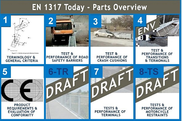
EN1317 is divided into different parts, each of which takes care of a different aspects or a different kind of product:
- EN 1317 Part 1: Terminology and general criteria for test methods
- EN 1317 Part 2: Performance classes, impact test acceptance criteria and test methods for safety barriers and vehicle parapets
- EN 1317 Part 3: Performance classes, impact test acceptance criteria and test methods for crash cushions
- ENV 1317 Part 4: Performance classes, impact test acceptance criteria and test methods for terminals and transitions of safety barriers *
- EN 1317 Part 5: Product requirements and evaluation of conformity for vehicle restraint systems
- TR 1317 Part 6: Pedestrian parapets
- TS 1317 Part 8: Motorcycle road restraint systems which reduce the impact severity of motorcyclist collisions with safety barriers
*ENV1317 Part 4 is going to revised, becoming an EN and being divided into:
EN1317 Part 4: Performance classes, impact test acceptance criteria and test methods for transitionsEN1317 Part 7: Performance classes, impact test acceptance criteria and test methods for terminals
Key Terminology
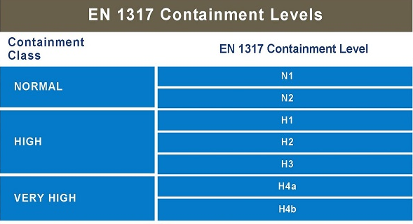
What is Containment Level?
Containment level indicateds the containment capacity of the system. Each containment level is defined by the crash tests that the road barrier has to withstand. Each new barrier has to be tested at least twice, once with a light vehicle in order to detect the severity of the impact on a small-size car and the second one with a heavier vehicle in order to define the maximum impact energy that the system can withstand. The containment levels are classified according to the growing energy of impact of the heaviest vehicle tested.
From the results of these crash tests, all the parameters defining the performance of the system are calculated.
A restraint system, in order to ‘pass’ the crash test, needs to fulfill a series of requirements:
- The safety barrier shall contain and redirect the vehicle without complete breakage of the principal longtitudinal elements of the system
- Elements of the safety barrier shall not penetrate the passenger compartment of the vehicle
- Deformations of, or intrusion into the passenger compartment that can cause serious damage are not permitted
- The centre of gravity of the vehicle shall not cross the centreline of the deformed system
- The vehicle must not roll over (including rollover of the vehicle onto its side) during or after impact, although rolling pitching and yawing are acceptable
- For tests with Heavy Good Vehicles, no more than 5% of the mass of the ballast shall become detached or be split during the test, until the vehicle comes to rest.
- Following impact into the safety barrier or parapet, the vehicle when bouncing back is not permitted to cross a line parallel to the initial traffic face of the system (see the definition of ‘redirection’ for more detail)
It is up to national regulations (and not the EN 1317) to define which are the containment level (at least the minimum) to be used in different situations according to specific criteria (traffic type, speed limit, presence of hazards on the roadside etc)
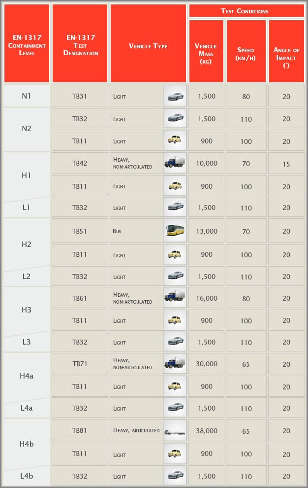
EN 1317 Containment Levels
EN 1317 Crash Test Specifications
 NB: Test TB11 and TB32 are designed to verify that the containment level by the barrier is compatible with the safety of the occupants of the vehicle.
What is Normalised Working Width?
Normalised Working width is a measure of the deformation of the barrier under impact. It is usually considered as the main parameter to calculate the space needed behind the barrier in order for the system to work properly. It is calculated as the maximum distance between the traffic face of the barrier and the maximum deformation of its main components during the impact of the heavier vehicle. The working width is divided into 8 classes from W1 to W8 according to the growing deformation of the system.
The table below provides an overview of the different working width classes and the equivalent values in meters.
 Ultimately, it is up to national regulations (not the EN 1317) to define the criteria that road designers should follow in order to choose the most suitable width class while designing the roadside.
What is Normalised Dynamic Deflection?
Normalised Dynamic Deflection is the second parameter to evaluate the deformation of the system under impact and it is calculated as the distance between the traffic face of the system in its initial condition and it maximum displacement. The dynamic deflection is measured in meters.
 It is up to national regulations (not the EN 1317) to define the criteria that road designers should follow to define the maximum dynamic deflection of the system to be used on the road, when designing the roadside.
What is Impact Severity?
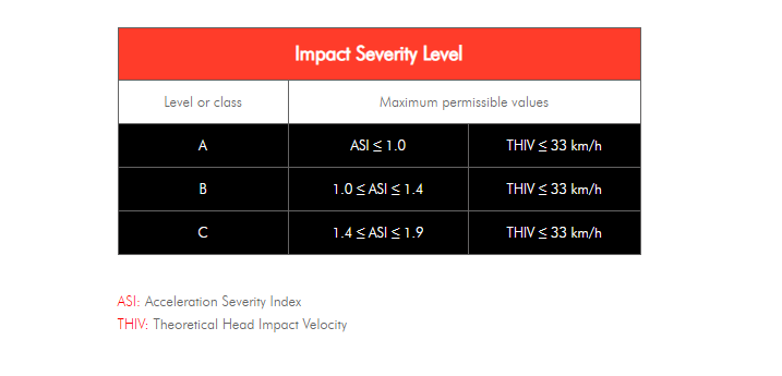
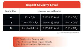
Impact Severity is an index that assesses the severity of an impact against the tested restraint system based on the results of different parameters. The impact severity is divided in 3 levels, from A to C, according to the growing severity of the consequences of the impact on the car’s occupant. The Impact Severity A affords a greater level of safety for the car’s occupants than level B and the same for level B compared to level C.
The Impact Severity is calculated by assessing two components: the Acceleration Severity Index and the Theoretical Head Impact Velocity
Acceleration Severity Index (ASI) is probably the main parameter for the calculation of the Impact Severity and is calculated by placing an accelerometer in the centre of the mass of the car and recording the impact against the road restraint system. The ASI is computed all along the impact time and its maximum value is used to evaluate the severity of the impact.
Theoretical Head Impact Velocity (THIV) has been developed for assessing the occupant impact severity for vehicles involved in collisions with road restraint systems. The occupant is considered to be a freely moving object (head) that, as the vehicle changes its speed during contact with the road restraint system, continues moving until it strikes a surface within the interior of the vehicle. The magnitude of the velocity of the theoretical head impact is considered to be a measure of the vehicle to road restraint system impact severity.
The table below show the different levels/classes of impact severity as well as the maximum ASI/THIV permissible values.
What is Redirection?
Redirection is the capacity of a restraint system to return a vehicle to the road in a controlled manner following impact against that same restraint system.

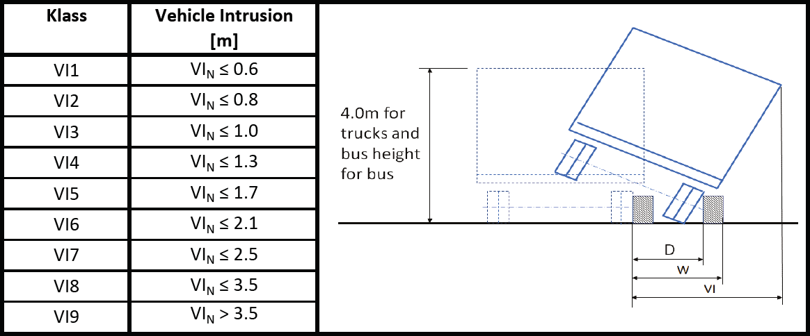
What is Vehicle Intrusion?
Testing carried out in compliance with EN1317-2: 1998 measured the VI to the maximum dynamic lateral position of the HGV (i.e. H1, H3, H4a and H4b vehicles), which may have had a flat bed, a curtain sided or a box sided construction, e.g. if a flat-bed vehicle was used then the VI would have likely been the same or slightly greater than the WW of the VRS. If the VI was recorded as a higher class than the WW, then the reported WW of the system would be based on this VI value.
Testing carried out in compliance with the updated EN1317:2: 2010 measures the VI to the furthermost part of the HGV which includes a notional load having the width and length of the vehicle platform and a total height of 4m from the ground. This addresses the ‘worst-case’ lean scenario for H1, H3, H4a and H4b HGV’s with different platform constructions.
The VI measurement for the H2 under EN1317-2:2010 remains unchanged from that in EN1317-2:1998, i.e. its maximum dynamic lateral position.
Hence in the testing of higher containment VRS’s (excepting H2) there could be an increase in the VI for H1, H3, H4a or H4b that has been reported to EN1317-2: 2010 when compared to the reported VI for an EN1317-2:1998 test.
In conclusion, it is suggested that all H1, H3, H4a and H4b VRS’s should have ALL the VI and WW variances stated on the CE mark to allow designers to produce effective and safe VRS layouts.

Crash Tests
This section is dedicated to displaying several crash tests of various road restraint systems products that are conducted according to the EN 1317. The crash test are categorised according to their containment level.
|
N1 |
N2 |
H1 |
H2 |
H3 |
H4b |
Update of hEN 1317-5
In 2012, the CEN published a major amendment of the EN 1317, which is the second since the approval of the standard in 2007. The goal of this amendment was to integrate in the harmonised part of the standard (Part 5) the changes already introduced in the supporting parts (1,2 and 3) since 2010. This was necessary in order for notified bodies to be able to award CE marks according to updated criteria.
The amendment also introduces performance classes concerning snow removal operations which concerns mainly Scandivian countries.
This section explains in a simple but concise manner the major changes introduced.
1. Removal of Post-Head Impact Deceleration (PHD)
In the 2007 version of the EN 1317, the Impact Severity was calculated by considering three distinct values:
– Acceleration Severity Index (ASI)
– Theoretical Head Impact Velocity (THIV)
– Post-Head Impact Deceleration (PHD)
EN 1317-5 2007
In the 2010 version, the PHD has been removed because, as a result of exentive empirical evidence, experts judged it to be unreliable as a parameter.
EN 1317-5 2012
2. Introduction of L-Class Containment levels
EN 1317 Crash Test Specifications – 2007 Version
In the 2007 edition of the EN 1317-5, the performance of the H-class barriers was evaluated by performing a test including a Heavy Good Vehicle(different for each class) and a small passenger car (the same test for all classes).
This meant a large percentage of ‘middle class’ vehicles currently circulating on the roads was not taken into account during the testing and subsequent certification of barriers, in particular family cars with an approximate weight between 1,500 kg and 2,000 kg.
As a result, the CEN working group introduced a new range of classes called ‘L-Class’ which as become a testing requirement and includes a third test of a middle sized vehicle to H-Class barriers. The introduction of these new barriers will ensure a higher level of safety for users on Europe’s roads.
EN 1317 Crash Test Specifications – 2012 Version
 3. Normalisation of deformation indices
In order to reduce the influence of the testing tolerances in the classification of performance of safety barriers, the deformation indices (working width, dynamic deflection, vehicles intrusion) are now normalised with the actual testing values for mass, speed and angle.